Note the control circuit is a three wire ladder diagram control circuit which works well for smaller horsepower three phase motors. It will also serve as a useful aid where simple wiring systems are to be studied.

Contactors Electromechanical Relays Electronics Textbook
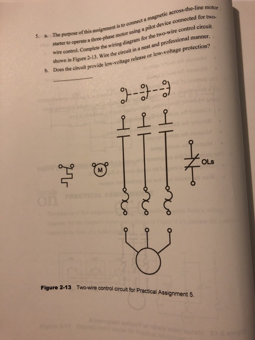
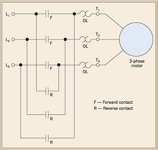
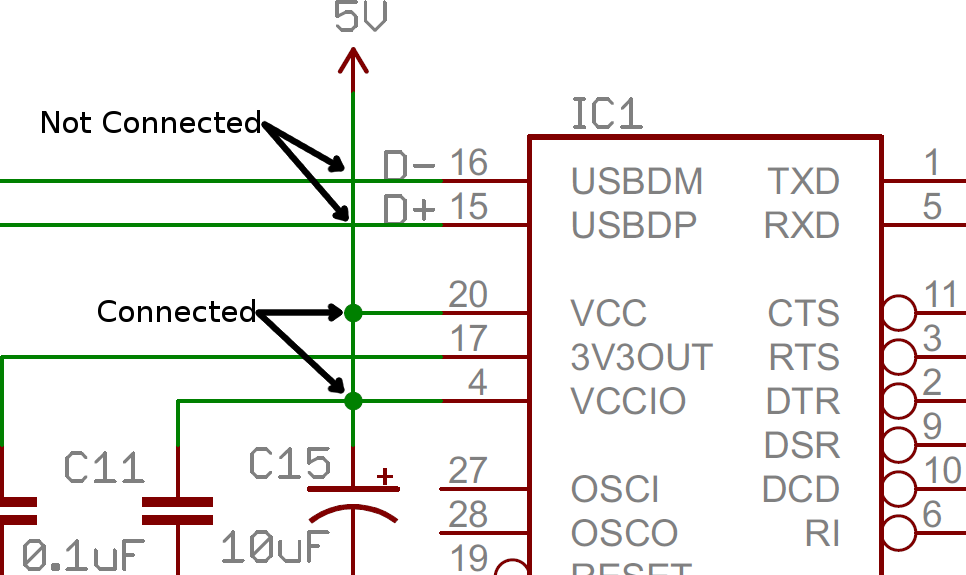
Across the line wiring diagram. Standard wiring diagram symbols if a line touching another line has a black dot it means the lines are connected. Electrical motors 12 lead dual voltage wye startdelta run both voltages or 6 lead single voltage wye startdelta run motors designed by us motors for wye start delta run may also be used for across the line starting using only the delta connection. Wiring diagrams ww introduction this booklet has been prepared as a guide to some of the useful ways allen bradleys manual and magnetic across the line starters may be applied. Motor wiring diagram us. This diagram shows both the power circuit and the control circuit. The more you work with both line and wiring diagrams the better you will become in analyzing them.
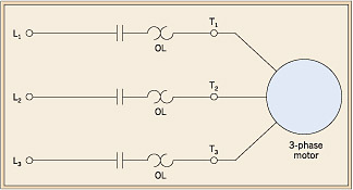
It is not difficult to learn the basic symbols. The diagram for a typical full voltage across the line starting circuit is shown in figure 1. Schematic diagram of the control and power circuits of the across the line magnetic starter. The across line magnetic starter is the simplest method of controlling 3 phase motor using a magnetic contactor see figure below. Both line and wiring diagrams are a language of pictures. Pictorial diagrams are often photos with labels or highly detailed drawings of the physical components.
Once you do you are able to read diagrams quickly and can often understand a circuit at a glance. When applying these diagrams it is well to. Unlike a pictorial diagram a wiring diagram uses abstract or simplified shapes and lines to show components.
Gallery of Across The Line Wiring Diagram