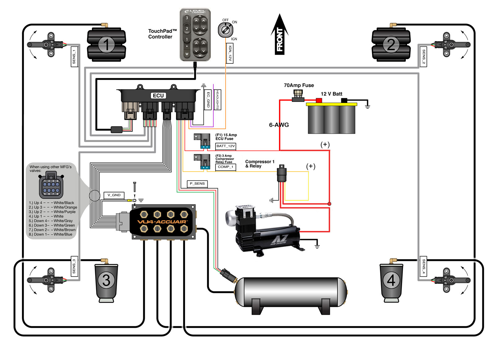
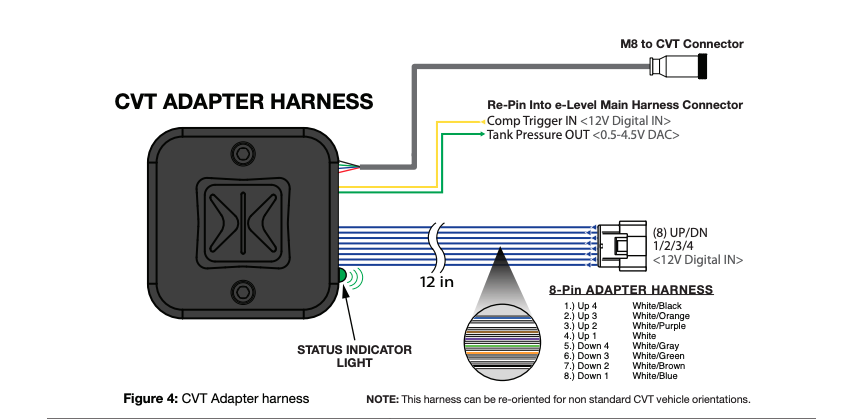
Page 1 to enhance the entire systems performance and reli ability the accuair e level also manages your air compressors to keep onboard air at an ideal pressure for your application. System diagram f1 10 amp ecu fuse batt12v main 50amp fuse intake filter ignition 12v tandem cvt wire top view standard cvt vehicle orientation figure 3.

24ac3 Car Speaker Wiring Diagram Two Wiring Library
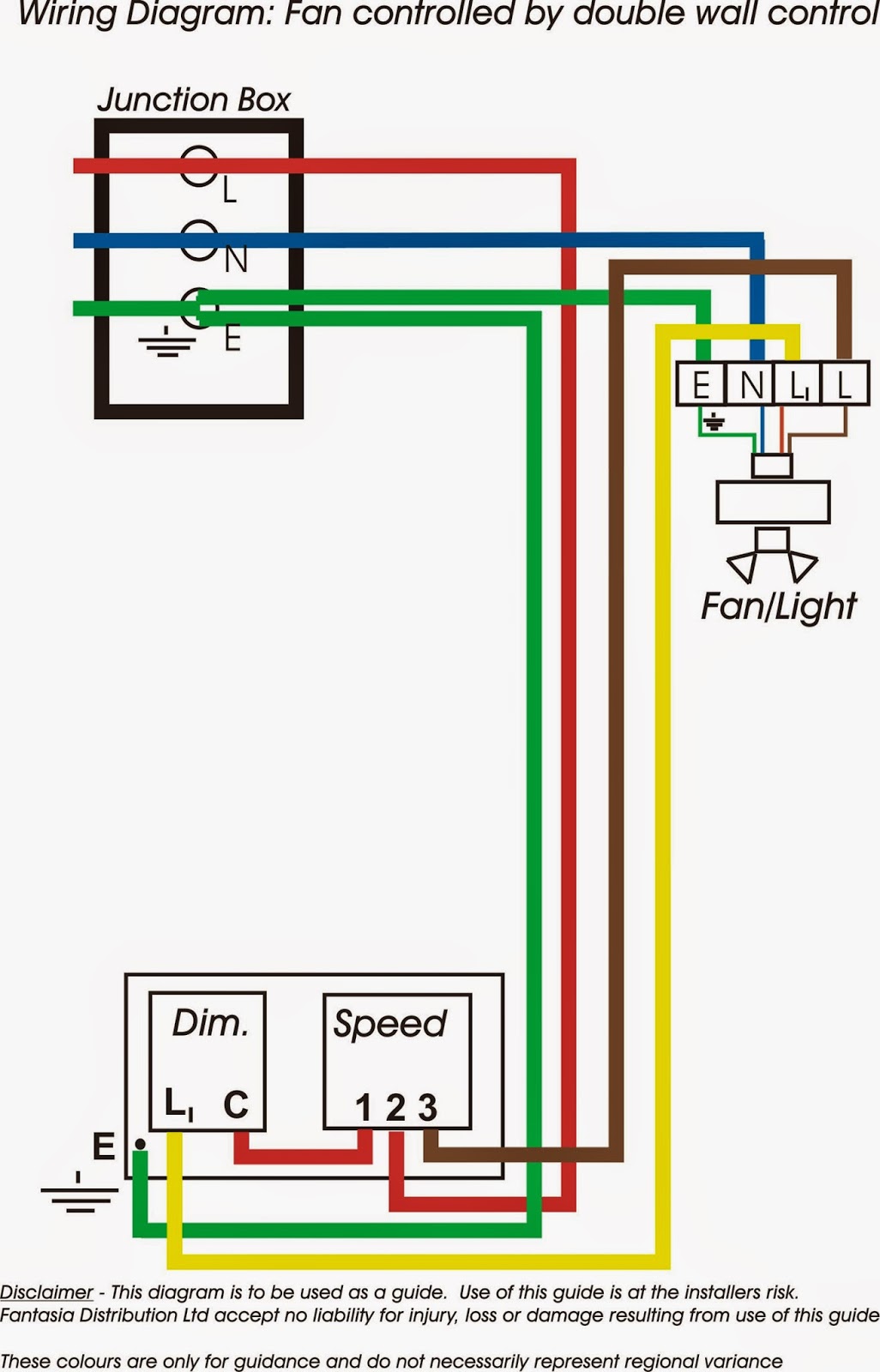
Accuair wiring diagram. 1 ride height the height that you will typically drive your vehicle at. It shows the components of the circuit as simplified shapes and the talent and signal connections amid the devices. Thermostat wiring diagrams for heat pumps heat pump thermostat wire diagrams. Architectural wiring diagrams discharge duty the approximate locations and interconnections of receptacles lighting and permanent electrical facilities in a building. Interconnecting wire routes may be shown approximately where particular receptacles or fixtures must be on a common circuit. Heat pumps are different than air conditioners because a heat pump uses the process of refrigeration to heat and coolwhile an air conditioner uses the process of refrigeration to only cool the central air conditioner will usually be paired with a gas furnace an electric furnace or some other method of heating.
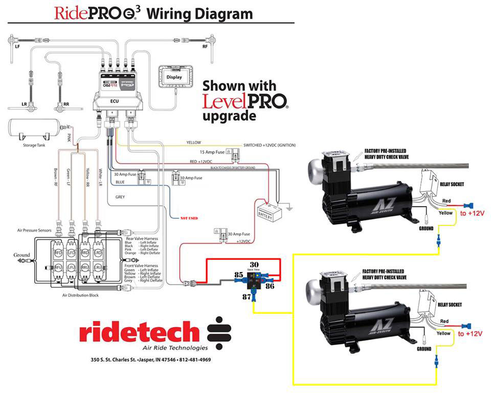
Cvt wiring and plumbing diagram page 5 endo cvt instructions v 12 accuair suspension 2018. 7 mount the single black wire labeled ecgnd with the vu4 ground. Quick view compare choose options. See system diagram on pages 4 5. See system diagram on pages 4 5. To maximize functionality the accuair e level allows you to select from three distinct vehicle heights through a rocker switch.
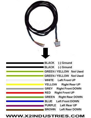
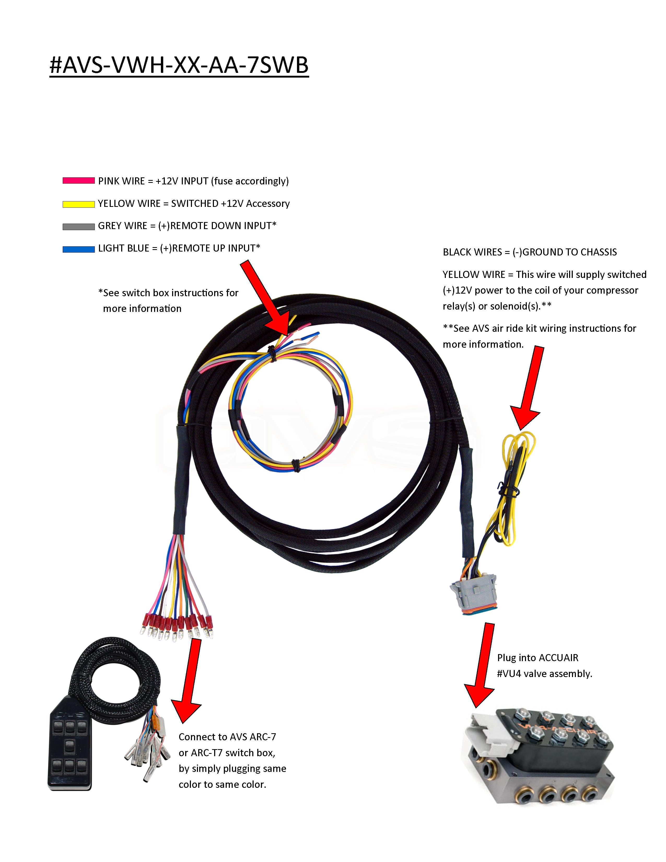
Avs valve wiring harness 10 15 20 accuair vx4 valve to avs 7 switch box. Quick view compare choose options. 7 mount the single black wire labeled ecgnd with the vu4 ground. Endo instructions v11 page 1 accuair suspension 2016 for and air pressure limits both endo t and endo vt are dot rated for 200 psi maximum pressure 136 barfailure to observe maximum rated pressure could result in tank rupture and consequent property damage or personal injury. Toro 580d wiring diagram wiring diagram article review. Accuair wiring diagram wiring diagram is a simplified standard pictorial representation of an electrical circuit.
6 route the single red wire labeled batt12v with a 15 amp fuse to the vehicle battery. 6 route the single red wire labeled batt12v with a 10 amp fuse to the vehicle battery. 8 route the single blue wire labeled e brake to the ground triggered e brake switch. 5 route the single yellow wire labeled comp1 to trigger the compressor relays. Valve wiring harness 10 15 20 accuair vu4 valve to stripped wires.
Gallery of Accuair Wiring Diagram