Unit operation the wiu 4 works with current microcontroller firmware versions and supports most. Wiegand interface unit four state wiu 4 installation manual connecting the wiu 4 connect the wiu 4 between the microcontroller and access control reader as indicated in figure 3 warning.

8rp Board Installation Sheet Utcfs Global Security Products
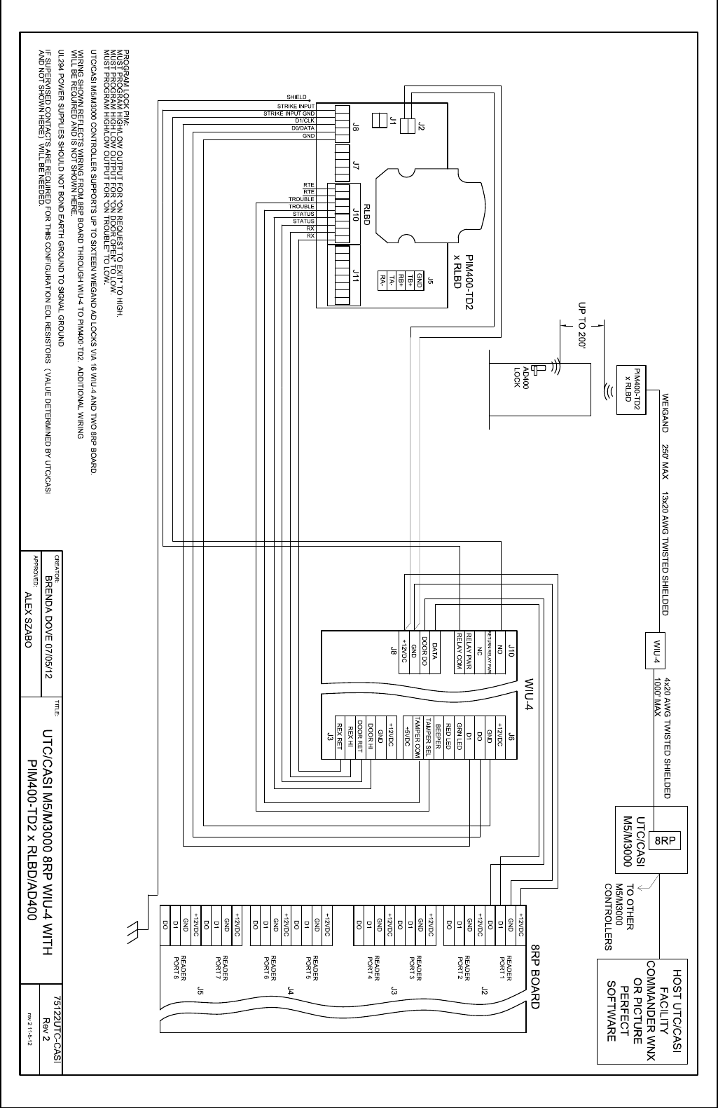
Wiu 4 wiring diagram. Refer to configuring the wiu 2 on page 8. Close circuit condition occurs between the wiu 4 request to exit rex and door data inputs di. It is important to ensure all connections are made prior to applying power. Refer to testing the wiu 2 on page 15. Connecting the wiu 4 15 wiring diagrams figure 4. The wiu 4 provides the communications interface that enables support of up to 16 wiegand output readers per microcontroller.
The wiu 4 provides a wiring union and wiegand to supervised f2f transfer point for use with ge access control systems. Wiu 4 to reader. Wiu 4 to micro5 8rp board wiegand interface unit four state wiu 4 installation manual 16 figure 5. Refer to connecting the wiu 2 on page 12. The wiu 2 must be mounted indoors in a protective enclosure or standard 1 gang electrical box installer supplied as shown in figure 1. The wiu 4 also bridges common wiring connections for junction box designs.
The maximum cabling distance of 250 ft 7620 meters is influenced by wire gauge reader power requirements minimum input voltage at the reader when using the 12 vdc from the wiu 4 originally from the micro and the cabling between the wiu 4 and micro. Verify reader j 6 doorrex j 3 door strike j 10 and micro j 8 connections are. Door contact rex door strike and alarm shunt outputs are all supported by the wiu 4. Wiu 4 to micropx 2000 pxn 2000 or m2000pxnplus interface testing the wiu 4 17 testing the wiu 4 1. Microcontroller the wiu 4 can be configured with a m2000 controller.
Gallery of Wiu 4 Wiring Diagram