Their field winding is powered by the dc power supply and is wired in series with the armature winding. These connections are in accordance with nema mg 1 and american standards publication 06.
Dc Motors
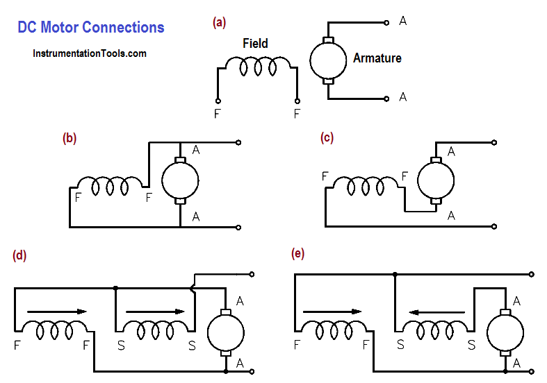
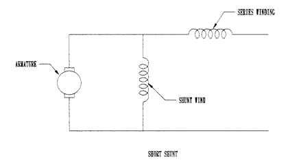
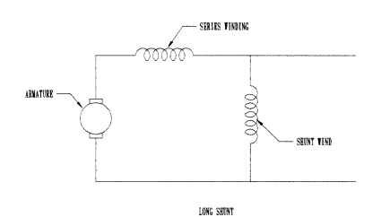
Series wound dc motor wiring diagram. A compound wound dc motor also known as a dc compound motor is a type of self excited motor and is made up of both series the field coils s 1 s 2 and shunt field coils f 1 f 2 connected to the armature winding as shown in the figure below. Dc series motor components used in dc series motor. Since the entire supply current flows through both the armature and field conductor. A wiring diagram usually gives opinion virtually the relative outlook and contract of devices and terminals upon the devices to put up to in building or servicing the device. Types of dc motor a direct current motor dc is named according to the connection of the field winding with the armaturemainly there are two types of dc motors. Notice how the field winding is connected in series to the rotor assembly.
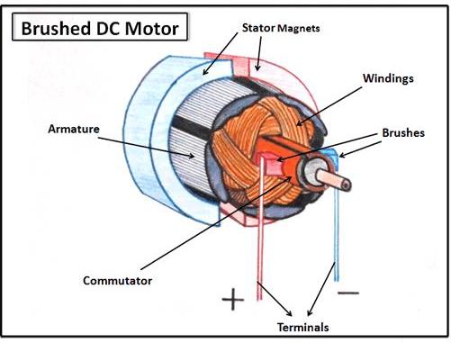
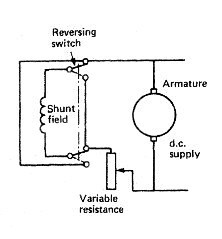
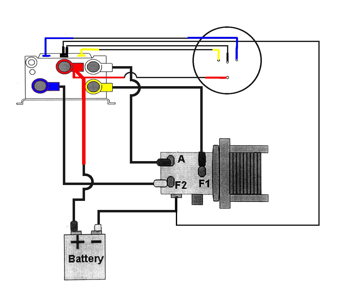
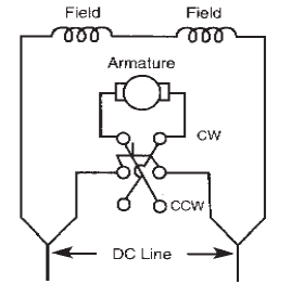
Use figure 1 if your motor has a single voltage shunt field. In this motor we have a large amount of starting torque so its the best with applications of dc series. The components of this motor mainly include the rotor the armature commutator stator axle field windings and brushesthe fixed component of the motor is the stator and it is built with two otherwise more electromagnet pole parts. Motor wiring diagram dc. Series wound dc motor. How to wire a dc series motor and how to reverse its rotation.
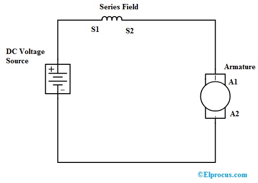
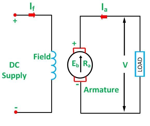
It shows the components of the circuit as simplified shapes and the facility and signal contacts together with the devices. First one is separately excited dc motor and self excited dc motor. The self excited motors are further classified as shunt wound or shunt motor series wound or series motor and compound wound or compound motor. Voltage and current equation of series dc motor the electrical layout of a typical series wound dc motor is shown in the diagram below. Use figure 2 if your motor has a dual voltage shunt field. Through examining figure 2 it becomes clear why these motors are known as series wound dc motors.
Let the supply voltage and current given to the electrical port of the motor be given by e and i total respectively. The simplified circuit diagram for series wound dc motors. Motor connections your motor will be internally connected according to one of the diagrams shown below. Series wound dc motor as we said before that this type of dc motor is a self excited dc motor which converts electrical power into mechanical power based on electromechanical law but in this motor the field winding is connected in series to the armature winding. I am also looking for information on controlling one of these motors with pwm pulse width modulation. Shunt wound dc motor wiring diagram wiring diagram is a simplified standard pictorial representation of an electrical circuit.
Gallery of Series Wound Dc Motor Wiring Diagram