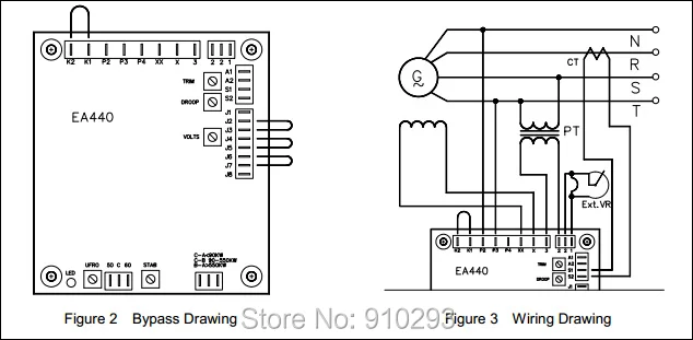
Diffor k2 k1 p2 p3 p4 xx x 3 2 2 1. You can save this picture file to your own personal pc.

Newage Avr And Stamford Test
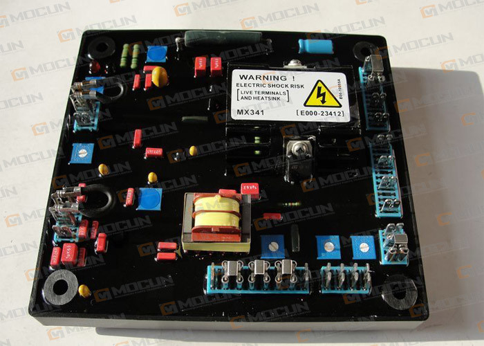
Mx341 2 avr wiring diagram. Stamford avk dm digital excitation control system french digital avr. A a mx avr for stamford generator by edgarcoo. Our people also have some more photos associated to stamford generator wiring diagram please see the photo gallery below click one of the. Regulator avr provision is made for the connection of a remote voltage. Wiring diagramfitting and operating refer to generator wiring diagram for connection details mx avr outline drawing figure 1 newage mx avr 5. See generator nominal frequency eg.
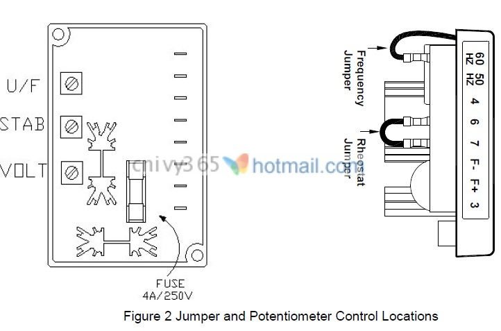
The avr controls are set at the factory for initial running tests. 00 v connect screen to avr terminal 2 only. Check that the avr settings are compatible with your required. Mx341 avr controls 32 initial avr setup notice the avr must be setup only by authorised trained service engineers. Mx341 is a two phase sensed automatic voltage regulator and forms part of the excitation system for a brush less generator. Download mx341 wiring diagram.
And operating refer to generator wiring diagram for connection details mx avr outline drawing figure 1. The mx is a two phase sensed automatic voltage. Do not exceed the designed safe operating voltage shown on the alternator rating plate. Mx341 automatic voltage regulator avr specification installation and adjustments general description mx341 is a two phase sensed automatic voltage regulator and forms part of the excitation system for a brush less generator. Self excited automatic voltage regulator compatible with newage mx. Please right click on the image and save the picture.
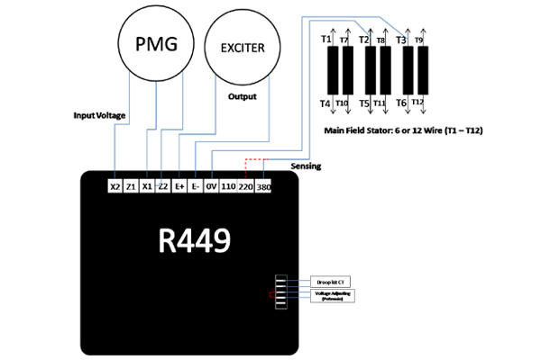
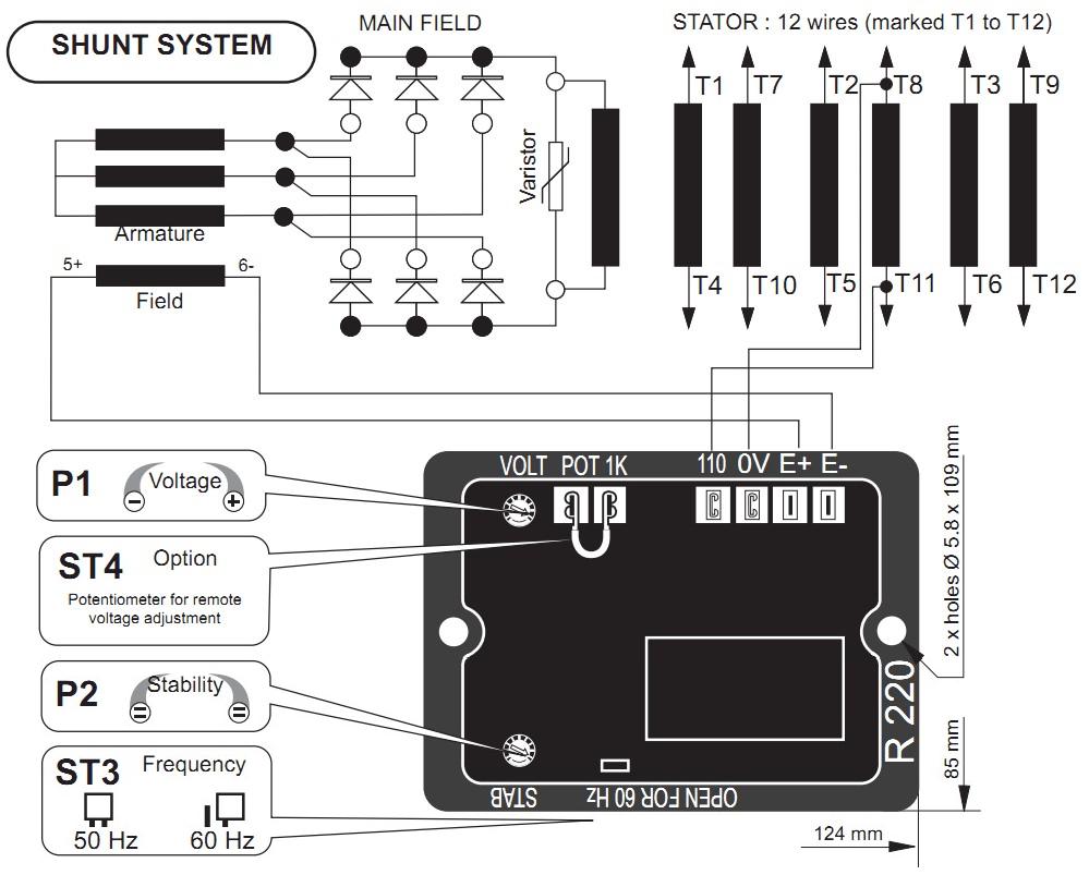
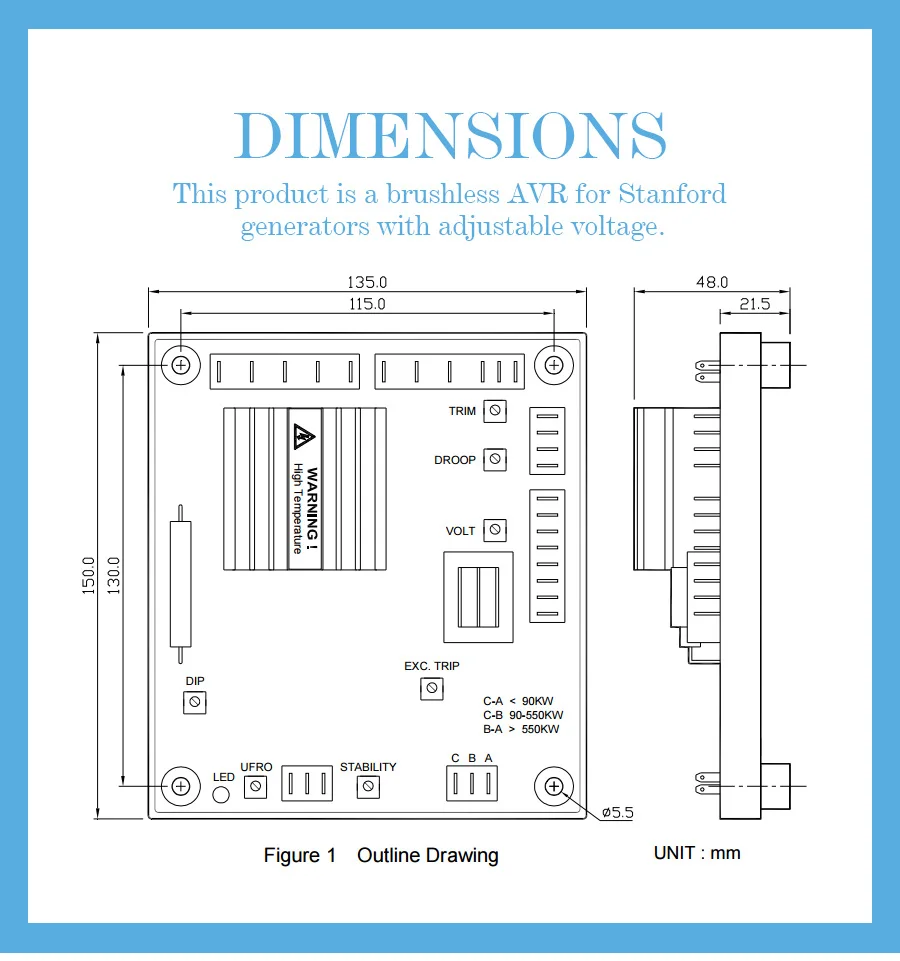
This is the stamford mx341 avr wiring diagram cabg diagram wiring diagram of a photo i get from the stamford generator wiring diagram collection. The mx avr is a two phase sensed automatic voltage regulator and forms part of the excitation system for a brush less generator. Proudly powered by. Excitation power is derived from a three phase permanent magnet generator pmg to isolate the avr control circuits from the effects of non linear loads and to reduce radio frequency interference on the generator terminals. 1 phase 2 wire frequency 50 60 hz nominal power input pmg voltage 140 220v ac max 3 phase 3 wire current 3aphase.
Gallery of Mx341 2 Avr Wiring Diagram