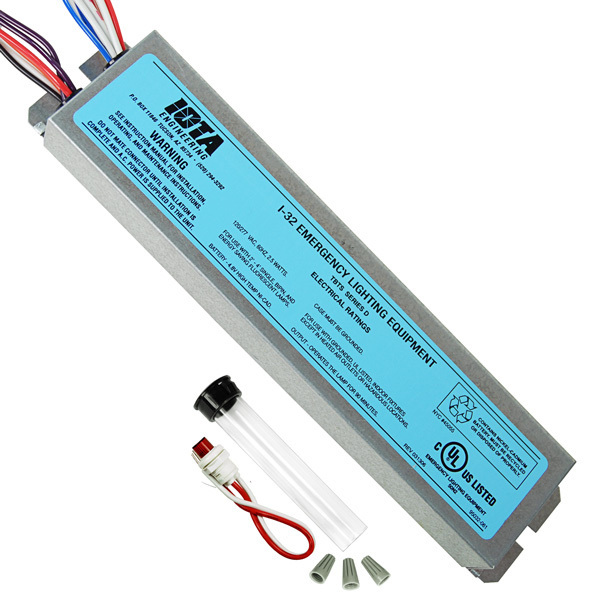
The i series acfluorescent emergency ballast from iota engineering allows the same fixture to be used for both normal and emergency operation. We attempt to discuss this iota emergency ballast wiring diagram pic here because based on information coming from google search engine its one of many top queries key word on.

2328b7 Emergency Lighting Ballast Wiring Diagram Wiring Library
Iota i 320 wiring diagram. Iota i320 emergency ballast wiring diagram architectural electrical wiring layouts reveal the approximate locations and also affiliations of receptacles lights as well as irreversible electric solutions in a building. The i 32 fluorescent emergency ballast from iota engineering allows the same fixture to be used for both normal and emergency operation. Ballast must be on the same panel board. Collection of iota i320 emergency ballast wiring diagram. The i 320 he from iota engineering is a ul listed emergency ballast that allows the same fixture to be used for both normal and emergency operation. In the event of a power failure the i 320 he switches to the emergency mode and operates one of the existing lamps for 90 minutesthe unit contains a battery charger and inverter circuit in a single can and can be mounted in the wireway or on.
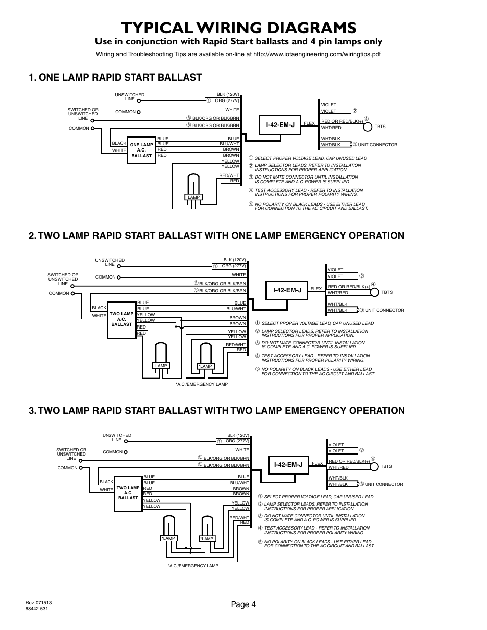
Iota 320 wiring diagram i tbts series ac emergency lighting equipment po. Ballast iota power suppliers. Refer to the wiring diagrams on the back page for the appropriate wiring of lamps and ballast. Adjoining cord paths may be shown about where particular receptacles or components have to be on an usual circuit. In the event of a power failure the i 32 switches to the emergency mode and operates one of the existing lamps for 90 minutes. The i 32 can be used with most 2 4 t8 thru t12 and.
The i 320 requires an unswitched ac. Most 2 4 single bipin t8 fluorescent lamps and 2 4 14w to 54w t5 ho and vho fluorescent lamps for use with select led retrofit tube lamps. 26092018 26092018 6 comments on iota i 320 wiring diagram. Refer to the wiring diagrams on the back page for the proper wiring. It reveals the parts of the circuit as streamlined forms and the power and signal connections in between the gadgets. Refer to illustration 3 for switched and un switched fixture wiring diagrams.
The unit contains a battery charger and inverter circuit in a single can. A wiring diagram is a streamlined conventional pictorial representation of an electrical circuit. Power source of either 120 or 277 volts. Iota i user manual page 5 insert ac. Therefore when used with switched fixtures the i 320 input must be wired ahead of the switch. Iota resource for i 320 information specification sheets instruction manuals wiring diagrams and more 1 lamp 1350 lumens.
See the led.
Gallery of Iota I 320 Wiring Diagram