Visionpro iaq total home comfort system 5 68 02871 4. Variety of honeywell th9421c1004 wiring diagram.

Visionpro Remote Indoor Sensor
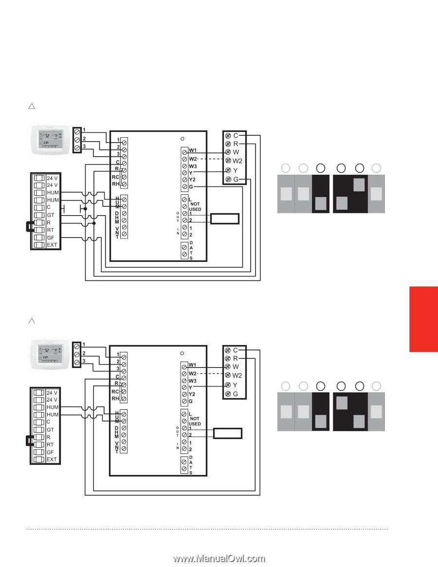
Honeywell iaq wiring diagram. Page 1 installation guide visionpro iaq equipment interface module english. Página 11 for up to 4 heat2 cool systems with honeywell thm5421c or equivalent. 12 wire eim as shown. 1 see wiring guideequipment section for iaq equipment wiring. Refer to the table and wiring diagrams on pages 3 5. It reveals the elements of the circuit as simplified forms and the power and signal connections in between the devices.
1 installing the equipment interface module eim terminal designations. Page 1 français. Wire at maximum of two sensors using the s1 s1 s2 s2 terminals. Wiring diagram for trueiaq internal control board conventional thermostat does not have to be honeywell i 5t fan hum hum hum setting on hum hum hum conventional power and system fan enforcement done via truesteam software setting hum hum hun title. If you are installing discharge and return air sensors refer to the mounting instructions in the alerts and delta t diagnostics installation instructions packed in the kit. Page 6 español.
The wiring diagrams for the iaq point 2 can be found on pages 13 16 of the user manual. Position the wallplate over the holes pulling wires through the wiring opening. 2 l terminal sends continuous output when thermostat is set to em. 3 3 1 compressor stage 1 compressor stage 2 return air sensor disharge air sensor indoor sensor outdoor sensor 2 return air sensor. System types gas oil or electric heat with air heat only conditioning heat only with fan warm air hot water high cool only. Insert the mounting screws into the holes and tighten.
A wiring diagram is a streamlined standard pictorial depiction of an electric circuit.
Gallery of Honeywell Iaq Wiring Diagram