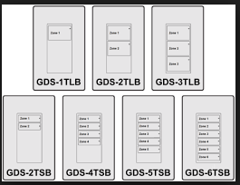
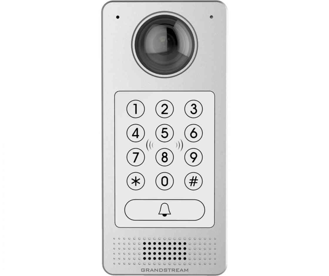
Gds greengate digital switch wwwcoopercontrolcom specifications communications canbus gds i kit is required for gds integration on all panels except the ckm size75h x 325w 121mm x 83mm descriptionoperation the digital switch permits multiple control stations to be connected to the lighting control panels. Wiring guide for this episode of gs tutorial were diving into how to wire a gds3710 with a magnetic fail safe lock and a door opening switch.
Hyundai Gds Diagnostic Amp Repair System Hyundai Car Service
Gds i kit wiring diagram. Where can i find a wiring diagram for greengate motion sensors with switchpacks. In the gds i box. What is the maximum length of cat 5 cable connected to a room controller device. Power supply for gds dc 12v 1a minimum 12v gnd power supply for electric strike dc 6 24v gds3710 power supply for gds v v v v in1 in1 gds3710 connection wiring diagrams fail safe electric strike 3rdparty power supply door lock switch com2 no2 nc2 in2 in2 fail safe model electric strike com1 no1 gnd to protect people. As always you can opt for our. Magnetic lock kit wiring.
Where can i get keeper enterprise software version 602. Gs tutorial gds wiring guide. Is there a distance restriction for 0 10v wiring. What is the position of the termination jumper on a gds i kit for on and off. Depending on the type of door lock and switch you select to pair with the gds will determine which wiring diagram to follow. Run this from the gds i into the low voltage section of the lighting control panel enclosure plugging the end with the 9 pin head into the gds i.
Black wire from gds i 24v to panel gnd red wire from gds i 24v to panel 24v. Plug the end of the rj11 phone style plug into the lighting panels designated digital switch port. Gs tutorials gds.
Gallery of Gds I Kit Wiring Diagram