Motion sensors to trigger the door to unlock. Push to exit button by enforcer brandmotion sensors.

How To Install A Push To Exit Button
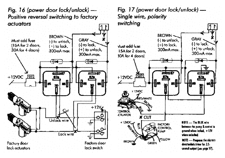
Enforcer push to exit wiring diagram. Enforcer outdoor piezoelectric request to exit pushbutton larm usa inc 3seco wiring the manual override. Keep as far away from wiring and metal as possible vel. Enforcer 100lb100cb installation manual page 4 enforcer 100lb100cb connection diagram chassis ground chassis ground antenna wire do not cut or ground 1. They are mounted right over the door at the inside of the door frame. Sd 6176 ssvq and sd 6276 ssvq only connect the manual override button with the included wires. The switch emits a cool green glow while in.
Regular wall mount push to exit buttons. Push to exit button wiring diagram. There are also panic exit devices such as push to exit bars. Remove the thin panel on the bottom of the plastic cover to allow wiring to pass through. Essex electronics stainless steel vandal resistant request to exit buttons can be used to control. Add to compare sd 7202gc peq led illuminated rte single gang wall plate w large green button 1224 vdc stainless steel.
Mower wire diagram online wiring diagram the contacts are ul listed with 10 amp capacity. The enforcer no touch request to exit sensor switch from seco larm uses ir technology to open a door or activate a device. Simply wave your hand in front of the switch up to 4 away and the ir sensor will detect the motion activating the built in relay. The enforcer post mount no touch sensor with access box is a full featured exit plate that uses ir t. Here is a quick video of how push to exit buttons work. Keep antenna straight up as high as possible 2.
Push to exit buttons mainly come in two types. Locksonline wiring diagram 004.
Gallery of Enforcer Push To Exit Wiring Diagram