At 230 volt 15 hp. This 3 pole iec rated contactor is rated for 10 hp.
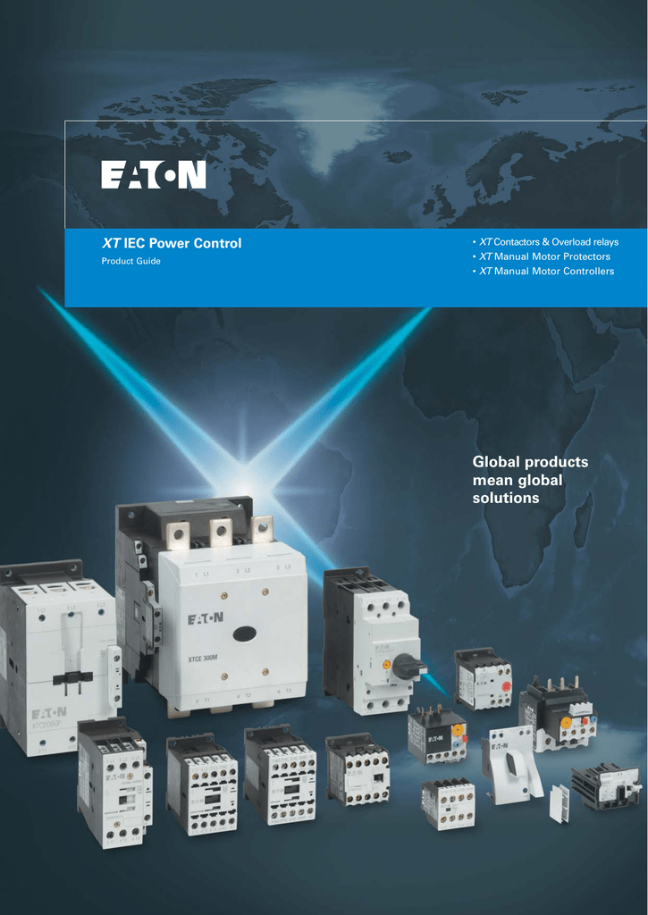
Global Products Mean Global Solutions Xt Manualzz
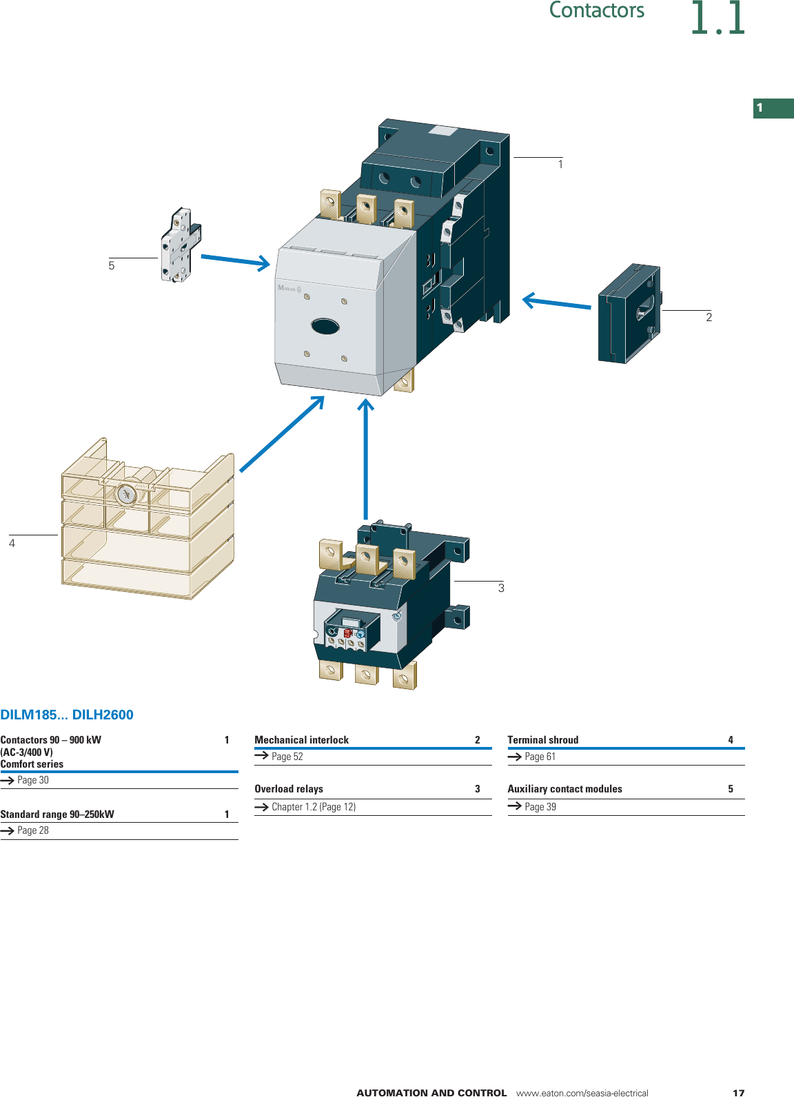
Eaton dilm25 10 wiring diagram. It reveals the components of the circuit as streamlined shapes and also the power as well as signal connections in between the tools. 1011 short circuit rating is the panel builders responsibility. For moeller dilm25 10 technical or sales support call the klockner moeller electric automation and motor control experts. Dilm25 10rdc24 contactor 3 pole 380 v 400 v 11 kw 1 no rdc 24. Contact sequences complete units. Moeller dilm25 10 is now eaton xtce025c10 contactor same exact part only part change.
A wiring diagram is a streamlined traditional photographic representation of an electric circuit. Ie a hp. Eaton will provide heat dissipation data for the devices. They can be used as a guide when wiring the controller. The common components in a wiring diagram are ground power supply cord and connection outcome gadgets switches resistors reasoning gateway lights etc. Dilm32 10230v50hz240v60hz contactor 3 pole 380 v 400 v 15 kw 1 no 230 v 50 hz 240 v 60 hz ac operation screw terminals.
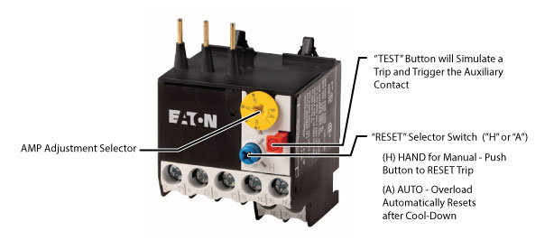
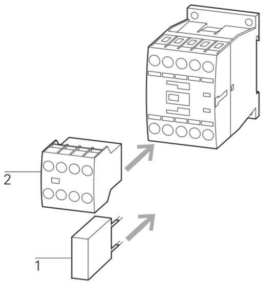
At 460 volt 3 phase and comes with screw terminals. Eatonmoeller dilm25 10 contactor with 24 volt dc rated coil 1 normally open base mounted auxiliary contact and is rated for 25 amps ac 3 40 amps ac 1. Eaton wiring manual 0611 5 1 55 contactors and relays page. 1010 temperature rise the panel builder is responsible for the temperature rise calculation. Figure 1 is a typical wiring diagram for a three phase mag. 1094 testing of enclosures made of insulating material is the panel builders responsibility.
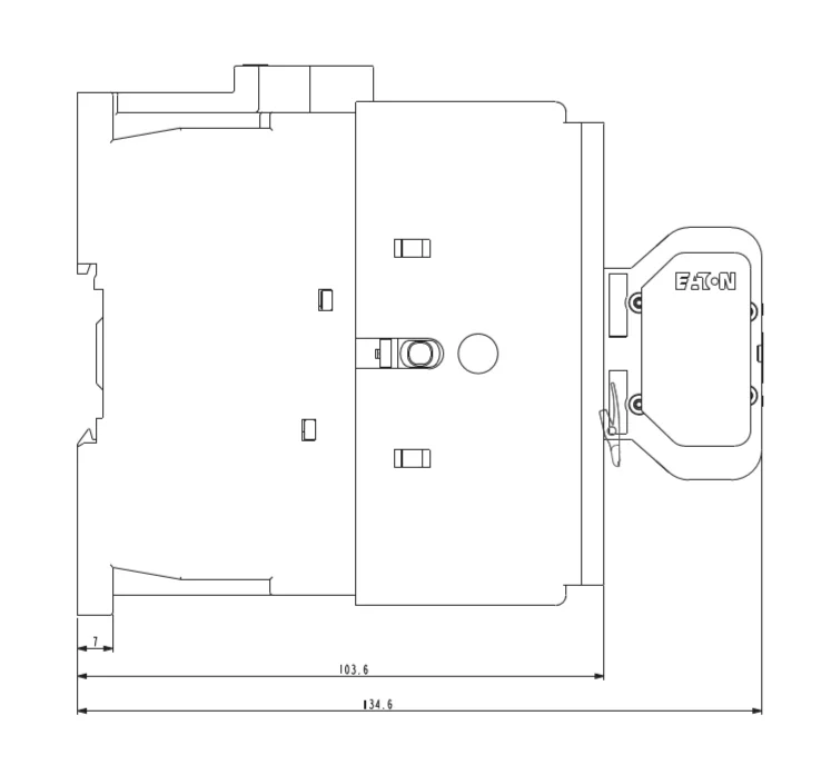
Inch to mm conversion. They show the relative location of the components. Eaton wiring manual 0611 5 7 55 circuit diagram damping also below u limit notes additional heat dissipation through circuitry. Collection of eaton motor starter wiring diagram. To check out a wiring diagram first you need to recognize what basic components are included in a wiring diagram as well as which pictorial icons are used to represent them. 24 27 v dc dc operation screw terminals 277146 dilm25 10rdc24 overview specifications resources.
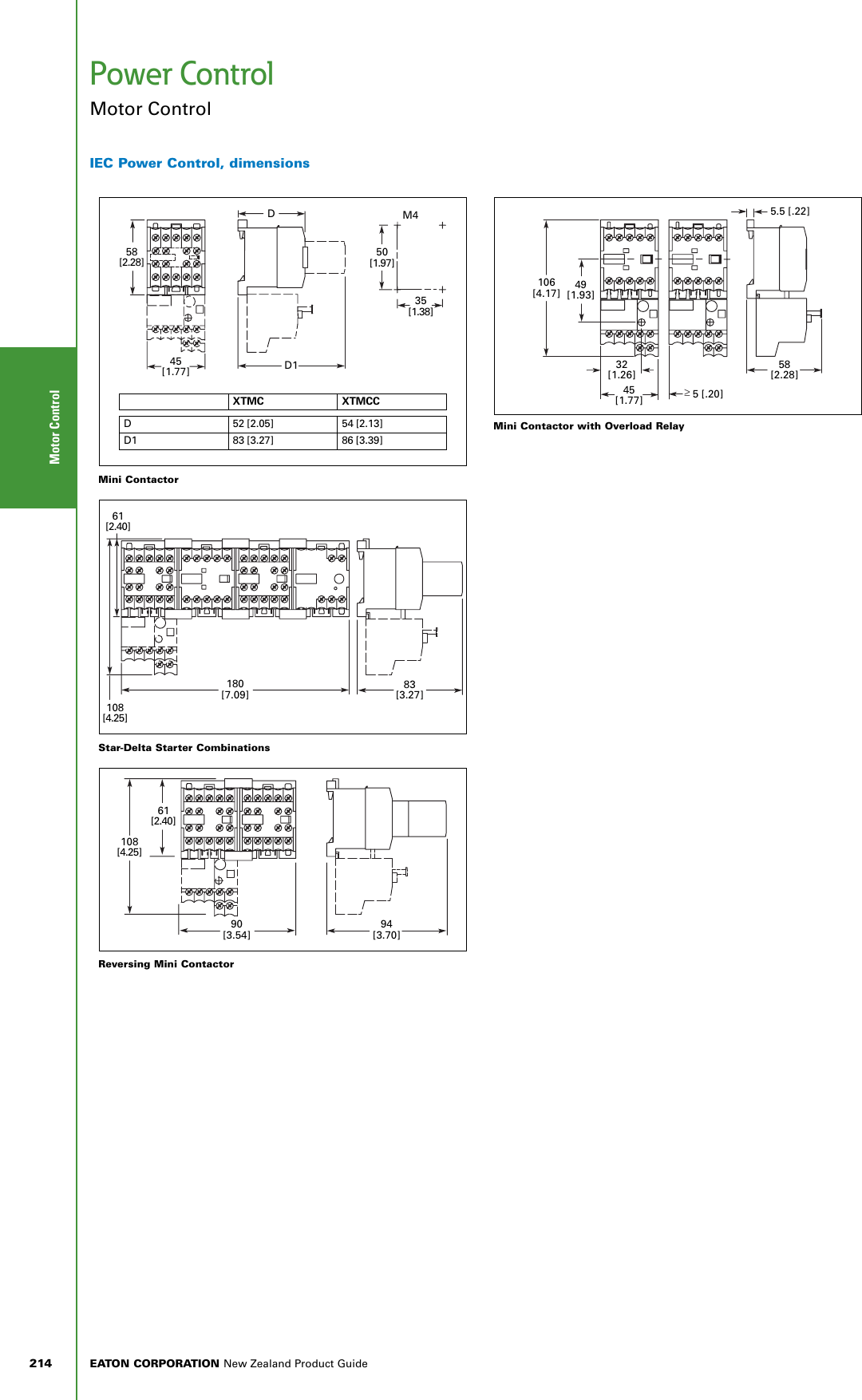
Wiring diagrams sometimes called main or construc tion diagrams show the actual connection points for the wires to the components and terminals of the controller. Eaton will provide heat dissipation data for the devices. Dilm25 10230v50hz240v60hz contactor 3 pole 380 v 400 v 11 kw 1 no 230 v 50 hz 240 v 60 hz ac operation screw terminals. 45 dilm25 32 10 15 17 45 dilm32 38 11 185 17 45 dilm38 40 125 185 23 60 dilm40.
Gallery of Eaton Dilm25 10 Wiring Diagram