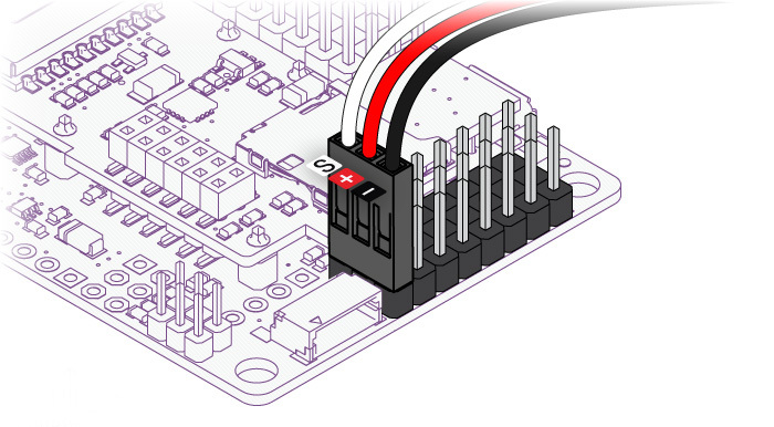
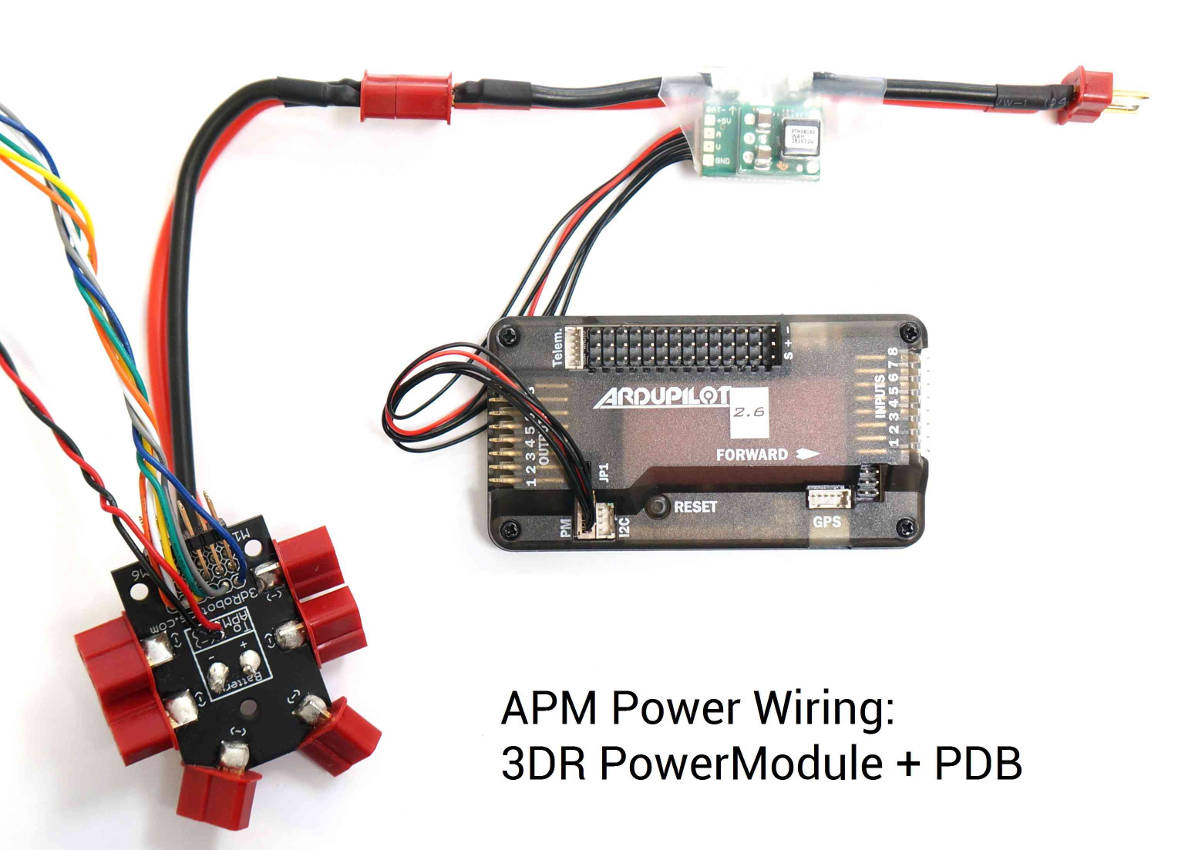
See the above link for additional detail. The diagram below is an overview of how an apm2 can be connected to a to apm output signal pins with the m1 wire connecting to the.

1b0 Apm 2 5 Wiring Diagram Wiring Library
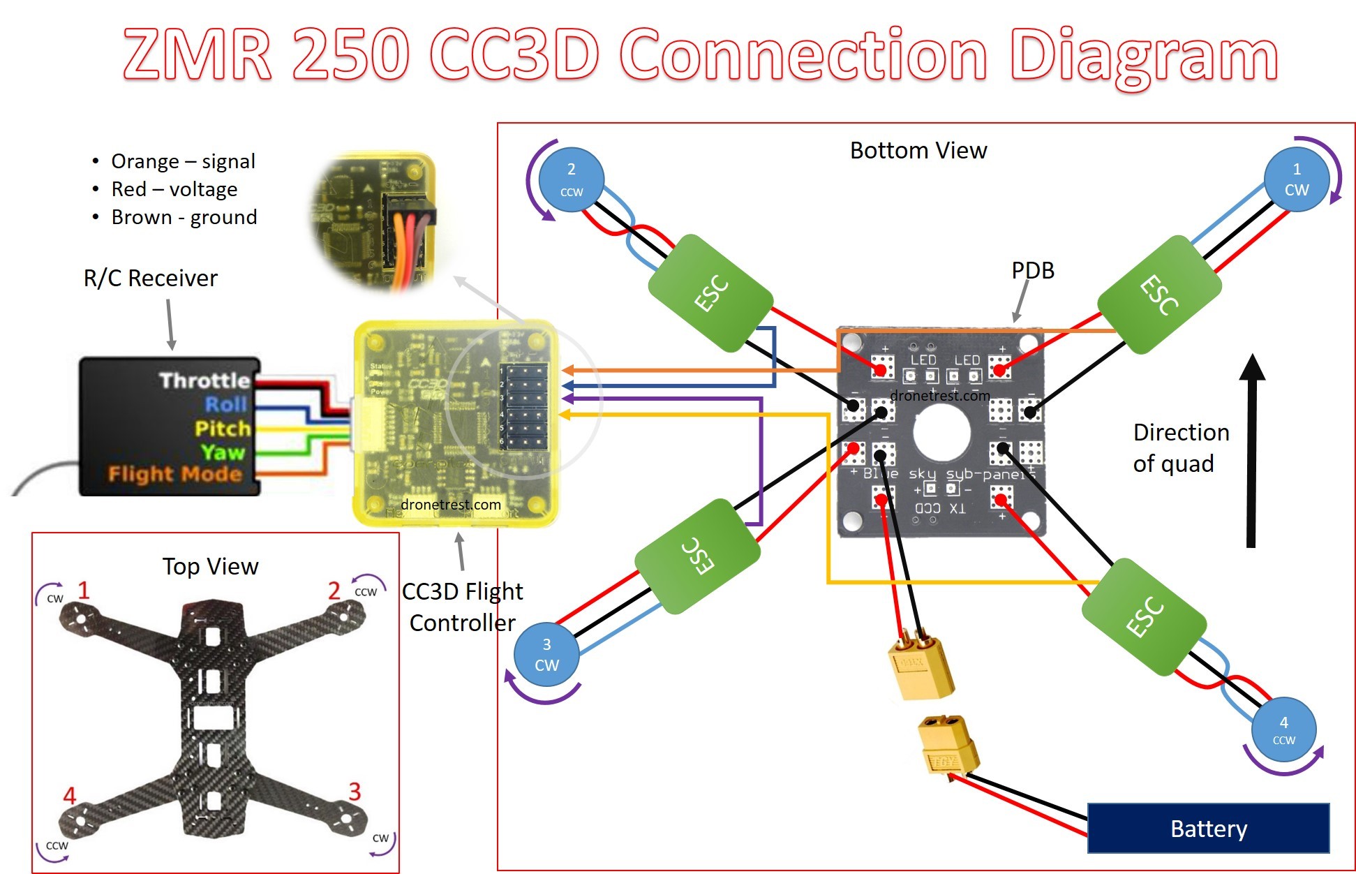
Apm 2 8 wiring diagram pdf. Download download apm 28 manual read online read online apm 28 manual mission planner pdfapm 28 motor layout ardupilot flight stack apm 28 barometer apm 28 manual download apm 26 schematic pdf arducopter 28 wiring apm 28 pinout. Auto pilot rc drone ardupilot apm ardupilot apm connect the ardupilot apm to the computer via usb cable. Texts pictures bookmarks links videos ive put together a manual from the arducopter wiki site for myself and would like to share with the assembly. Apm wiring diagram wiring diagram is a simplified okay pictorial representation of an electrical circuitit shows the components of the circuit as simplified shapes and the capacity and signal associates amongst the devices. Connect the pdb multi wire cable to apm output signal pins with the m1 wire connecting to the signal pin labeled 1 m6 and signal pin 6 etc. Find deals on ardupilot in electronics on amazon.
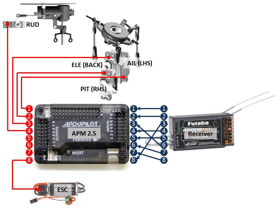
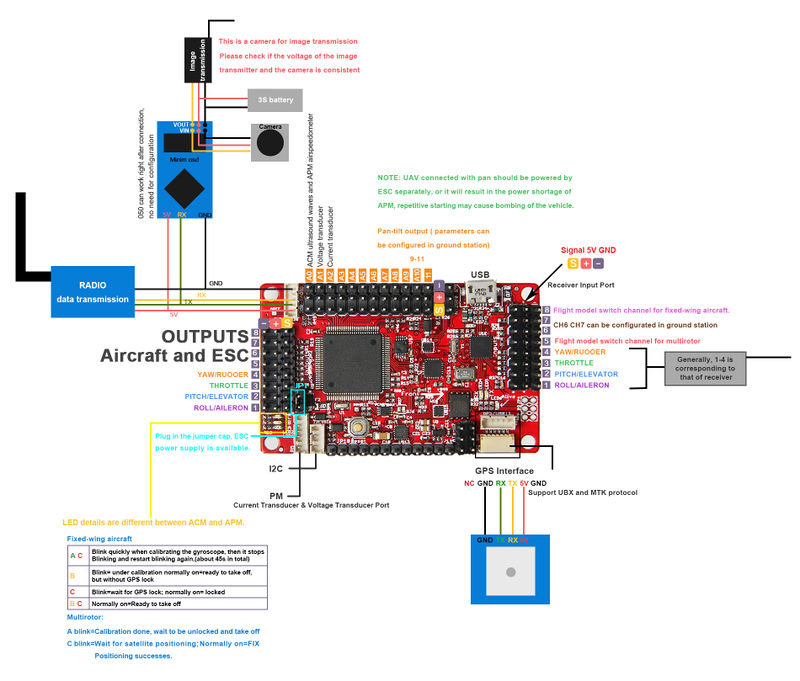
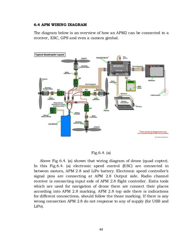
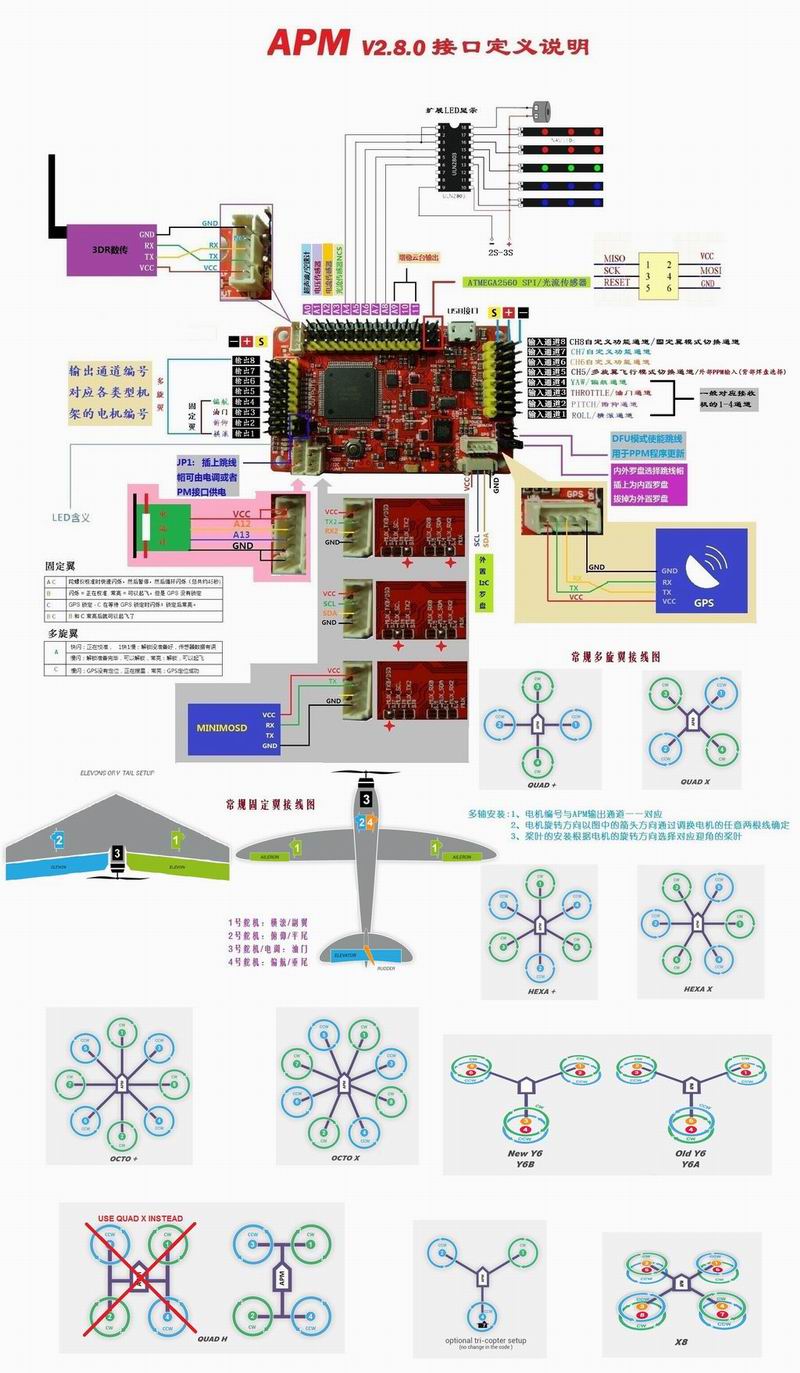
Apm 26 receiver wiring apm 26 schematic pdf apm 28 manual pdf arducopter 28. Heartly thanks for watching this video. Apm wiring diagram the diagram below is an overview of how an apm2 can be connected to a receiver esc gps and even a camera gimbal. Apm wiring diagram the diagram below is an overview of how an apm2 can be connected to a receiver esc gps and even a camera gimbal. Hello guys in this video you will quick learn about apm 28 setup installation esc wiring part 1 100 successful latest 2019 ii full video tutorial. The diagrams on the page below is for v1 and v2 which have molex clickmate.
27112018 27112018 5 comments on apm 28 wiring diagram. Connections between rc receiver and ardupilot mega v2 board this can be dune by cutting the red wire on all but one of the escs or by using a specialjan 20 at tim dickinson the op has the apm which is a clone and its different from apm pin layout. Before you can configure your arducopter you will need to first connect everything together. You still need an esc example wiring diagram for a bixler plane with apm. Connect the pdb multi wire cable to apm output signal pins with the m1 wire connecting to the signal pin labeled 1 m6 and signal pin 6 etc. Apm 28 wiring diagram.
The instructions below are for regular rc receivers with pwm output one cable per channelif youre using a ppm receiver one cable carries all channels follow the instructions here. A wiring diagram usually gives opinion about the relative aim and conformity of devices and terminals on the devices to incite in building or servicing the device. Apm 26 wiring wiring diagrams 19 apm 26 vs 28 wiring diagram ardupilot mega 2.
Gallery of Apm 2 8 Wiring Diagram Pdf